HOMEPRODUCTELECTRONICSEVC6-IR
* DISCONTINUED.
[EVC6-IR]
- Basic performance as a boost controller is the same as EVC6.
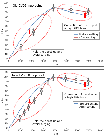
Correction map grid point is enlarged to 10×10.
Pressure correction range is increased to ー180~180.
More precise correction is possible for modern smaller sized turbo. - EVC6's TFT full color monitor is upgraded for better visibility with a new color pattern.
- Monitor Navigation System easily leads the user to the correct setting and logging screens.
- The proven Stepping Motor is utilized as a valve unit.
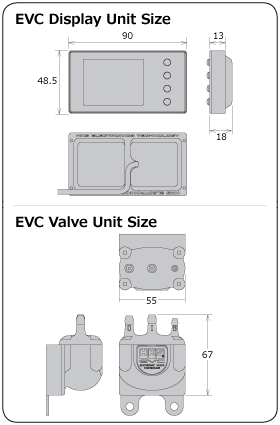
■ DISPLAY

■ FUNCTIONS
![]()
Boost pressure setting returns to stock pressure value when the unit is off.
![]()
Speed signal input enables the boost control with the speed. (500km/h)
![]()
The boost pressure can be increased by a designated value above the set value.
![]()
Input of the throttle signal and engine RPM or vehicle speed signals enables the boost control by a 3D map using 2 these signals as axes.
![]()
Boost pressure can be set in 3 different modes to use them for different conditions.
![]()
3 digital data readings of surge tank pressure and throttle angle, engine RPM or vehicle speed can be displayed in real time.
![]()
The differences between the boost pressure set value and actual value can be offset in 3 different modes. This ensures more precise setting.
![]()
Select the type of a bar graph from the boost pressure, throttle angle, engine RPM and vehicle speed.
![]()
If the boost exceeds the warning value, an audible beep and visible warning display notify the user. Also, the boost is lowered to the stock value or a preset value to prevents damage to the engine.
![]()
The bar graph displays the maximum value after it is reached. It can achieve easy instant recognition.
![]()
Throttle position sensor signal input enables the boost control with the throttle angle.
![]()
The maximum positive boost value is displayed for 3 seconds when the boost changes from positive pressure to negative pressure.
![]()
Engine RPM signal input or ignition signal input enables the boost control with the engine RPM.
(1 to 8 cylinders/up to 12000rpm)
![]()
All settings are stored in the internal memory; so settings will not be lost even when the ignition is off or the battery is disconnected.
![]()
Select the display unit's brightness from 2 levels.
![]()
Select appropriate exhaust bypass type from swing valve type or poppet valve type.
![]()
Data can be locked with a password; it prevents data loss or inadvertent data changes.
![]()
Select the unit from kPa or PSI.
![]()
The side of the buttons can be switched by flipping the monitor vertically.
NEW FEATURES
New Color Pattern TFT LC Display
Redesigning the color pattern of the main display improved the visibility during driving.
Segmentalized Correction Map
Enlargement of the correction map grid point to 10 × 10 from 5×5 enables more precise correction.


